As far as the high rigidity structure is concerned, the finite element analysis software has been used for auxiliary design, static and dynamic structure analysis of the casting, which ensures the high rigidity of the whole structure.


| Standard Configuration | Optional Configuration |
| Vertical Type | |
| FANUC CNC system | FANUC/Siemens/Heidenhain CNC Controller |
| BT40 12000rpm Spindle | BT/ISO/HSK-A63 10000~30000rpm Spindle |
| Spindle Direct Drive | |
| Spindle Oil Chiller | |
| Spindle coolant nozzle system | Coolant Through Spindle (CTS) |
| High Precision Screw rod | Coolant Through Screw rod |
| XYZ Axis Linear rails | |
| XYZ Axis Servo Motor | |
| Fully Enclosed Splash Guard | |
| Electrical Cabinet Heat Exchanger | Electrical Cabinet AC |
| Handheld air gun | |
| Water gun | |
| Automatic lubrication system | |
| LED working lamp | |
| Tool magazine | ATC/Tool Magazine system |
| CNC Manual & Operation | |
| Chip flush coolant system | |
| LCD | |
| Working lamp | |
| Three-color warning lamp | |
| Transformer(According to Local Voltage) | |
| Took kit | |
| The 4th axis rotary table | |
| spiral type Chip Conveyor system | |
| Chain type Chip Conveyor system | |
| Linear Scale | |
| Auto.Tool Measuring system | |
| Auto.Workpiece Measuring system | |
| CE Mark | |
| Others Options as requested |
High Rigid Structure
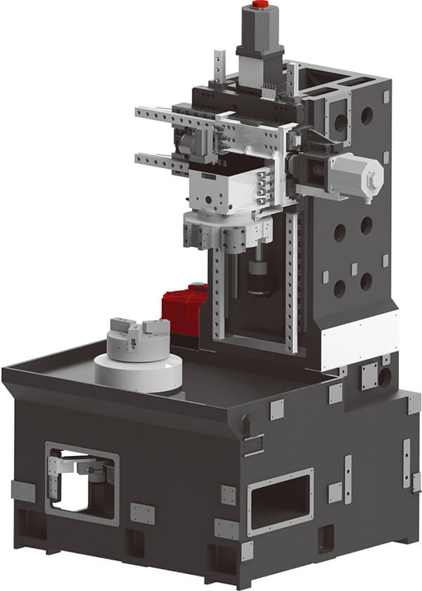
High Rigid Structure
High Precision Linear guide
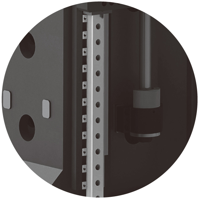
High Precision Linear guide
The X Y Z axis adopt heavy duty linear roller guide rail. They are of good rigidity, high accuracy and long service life
High Speed Spindle
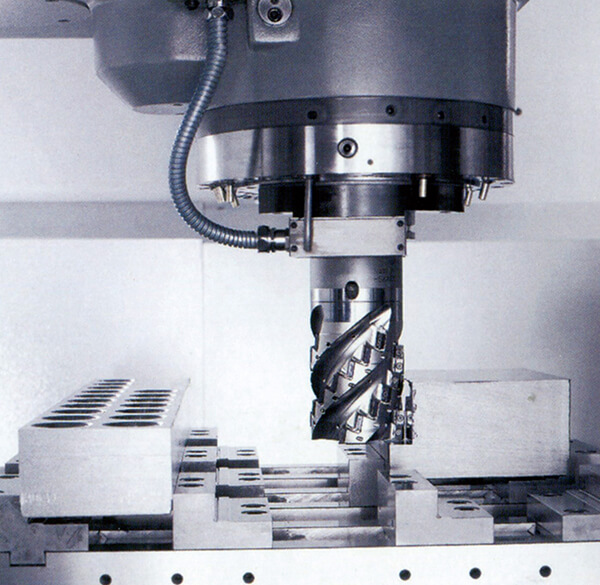
High Speed Spindle
The Machining center adopts direct drive spindle what gives high speed.
CNC system
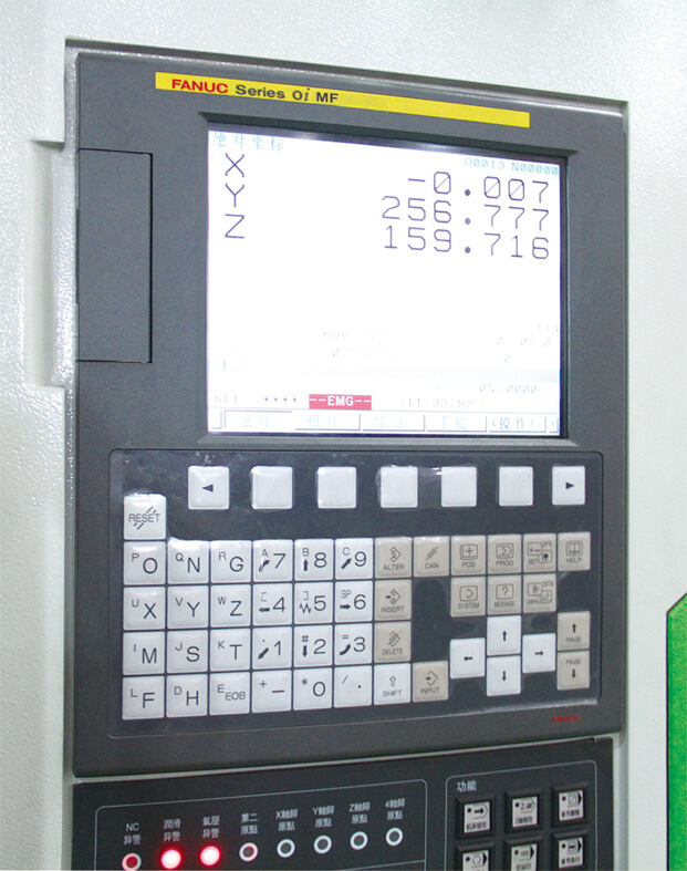
CNC system
Interpolation: the backlash interpolation, quadrant error interpolation, tool length interpolation, tool radius interpolation, temperature interpolation (optional).
Feed function: feed rate trimming, feeding rate per minute per rotation, feed rate, programmable acceleration limit.
Spindle function: spindle speed, spindle override function trimming, spindle orientation quasi stop, speed limit.
Tool Magazine
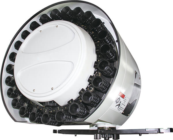
Tool Magazine
Automatic Tool Changer(ATC) is composed of tool magazine and tool changing arms. Automatic too changer is installed separately from machine tool with the purpose of preventing adverse influences of vibration during running of automatic tool changer and other reasons on precision. Tool selection adopts the method of fixed address in the shortest path. All tools return to original position, therefore, the problem of collision between large-size tools is only considered in initial installation. Two-way tool magazine adopts the shortest path.
Coolant Through Spindle (CTS)optional
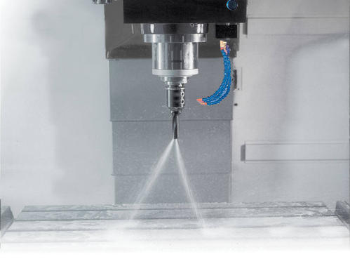
Coolant Through Spindle (CTS)optional
Because of the cold inside the hollow spindle coolant spewing from the tools, can directly effect on the workpiece and cutting tool parts, cooling effect is better than ordinary spindle, make better surface quality of machined part.
-
Parameter table
iHT 3 iHT 5 iHT 6 iHT 10 Spindle head FL 140 h5 FL140 FL170 h5 FL220 h5 Spindle maximum speed rpm/min 4500/5000 4500/5000 3250/4000 3000 Torque 40% ED N·m 112 112 300/370 540/630 Spindle power kW 7.5-11/11-15 11-15 15/18.5 15/18.5/22/33 Chuck diameter mm 6′/8′ 6′/8′ 10′/12′ 10′/12′ Spindle bore mm ¢74.3 ¢74 ¢87 ¢102 Front bearing diameter mm ¢100 ¢100 ¢130 ¢140 Spindle bearing lubrication Grease Grease Grease Grease Speed range rpm 5-5000/5-6000 4500/5000 5-3250/5-4000 5-3000 Working area Maximum swing over bed mm 558 550 650 680 Maximum swing over cross slide mm 420 320 400 465 Maximum cutting diameter over bed mm 340/328 390/340 450/420 515/465 Maximum bar capacity mm 42/51/65 42/52/65 65/75 75/90 Maximum machining length mm 350 500 550 1000 Travel Z mm 380 540 600 1050 Travel X mm 180 230 267 300 Center distance mm 608 700 787 1252 Ballscrew X / Z axies ballscrew D x P mm 32×10 32×10 38×10 40×10 Turret slide Rapid traverse Z m/min 30 30 30 30 Rapid traverse X m/min 30 30 30 30 Rapid traverse C m/min 100 100 100 100 Measuring system X/Z axies measuring system Absolute rotative Absolute rotative Absolute rotative Absolute rotative Positioning (X/Z) mm 0.008/0.008 0.008/0.008/0.010 0.008/0.008 0.008/0.010 Repeatability (X/Z) mm 0.004/0.005 0.005 0.005/0.005 0.005/0.005 Tailstock Stroke mm 350 500 500 850 Tailstock moving CNC Hydraulic / servo Hydraulic / servo Hydraulic / servo Hydraulic / servo Pressure N 4,000 4,000 8,000 12,000 Centre location MK 4 MK 4 MK 5 MK 5 Tool attachments Servo turret INVESTA/SAUTER INVESTA INVESTA/SAUTER INVESTA/SAUTER No. of tool stations 8-12 12 8-12 12 Turret disk type Slot type Slot type Slot type Slot type Tool attachment □25 □25 □25 □25 Driven tool turret SAUTER SAUTER SAUTER SAUTER No. of tool stations 12 12 12 12 Turret disk type BMT55 BMT55 VDI40/BMT55 VDI40/BMT55 Tool attachment □25 □25 □25 □25 Maximum speed rpm/min 4000 4000 4000 4000 Drive power (40 % DC) kW 3/3.3 3/3.3 3/3.3 3/3.3 Torque (40 % DC) 35/50 35/50 45/50 45/50 Electrical specifications Voltage V 380 ±10% 380±10% 380±10% 380±10% Frequency HZ 50 ± 1% 50 ± 1% 50/60 50/60 Max. installed power KVA 20/25 35 35 35/50 Hydraulic unit Max. working pressure bar 40 40 55 55 Reservoir capacity L 35 35 15 15 Pump flow L/min 24 24 24 24 Coolant system Capacity with tank L 100 150 150 175 Pump delivery L/min 30 30 30 30 Pump pressure bar 5 5 5 5 Control system FANUC 0i-TF 0i-TF 0i-TF 0i-TF SIEMENS 808/828/840D 828D/840D 828D/840D 828D/840D Others Noise level dB ≤80 ≤80 ≤80 ≤80 Net weight kg About 3,200 About 3,500 About 5,200 About 7,500 Size (length×width×height) mm About 3600×1850×1850 About 3750×1850×1800 About 3870×2000×2000 About 5100×2100×2100 Slant angle, Material ° 45°HT300 45°, Cast-iron 45°HT300 45°HT300 -
High Rigid Structure
High Rigid Structure
As far as the high rigidity structure is concerned, the finite element analysis software has been used for auxiliary design, static and dynamic structure analysis of the casting, which ensures the high rigidity of the whole structure.
-
High Precision Linear guide
High Precision Linear guide
The X Y Z axis adopt heavy duty linear roller guide rail. They are of good rigidity, high accuracy and long service life
-
High Speed Spindle
High Speed Spindle
The Machining center adopts direct drive spindle what gives high speed.
-
CNC system
CNC system
Interpolation: the backlash interpolation, quadrant error interpolation, tool length interpolation, tool radius interpolation, temperature interpolation (optional).
Feed function: feed rate trimming, feeding rate per minute per rotation, feed rate, programmable acceleration limit.
Spindle function: spindle speed, spindle override function trimming, spindle orientation quasi stop, speed limit.
-
Tool Magazine
Tool Magazine
Automatic Tool Changer(ATC) is composed of tool magazine and tool changing arms. Automatic too changer is installed separately from machine tool with the purpose of preventing adverse influences of vibration during running of automatic tool changer and other reasons on precision. Tool selection adopts the method of fixed address in the shortest path. All tools return to original position, therefore, the problem of collision between large-size tools is only considered in initial installation. Two-way tool magazine adopts the shortest path.
-
Coolant Through Spindle (CTS)optional
Coolant Through Spindle (CTS)optional
Because of the cold inside the hollow spindle coolant spewing from the tools, can directly effect on the workpiece and cutting tool parts, cooling effect is better than ordinary spindle, make better surface quality of machined part.
- French
- German
- Portuguese
- Spanish
- Russian
- Japanese
- Korean
- Arabic
- Irish
- Greek
- Turkish
- Italian
- Danish
- Romanian
- Indonesian
- Czech
- Afrikaans
- Swedish
- Polish
- Basque
- Catalan
- Esperanto
- Hindi
- Lao
- Albanian
- Amharic
- Armenian
- Azerbaijani
- Belarusian
- Bengali
- Bosnian
- Bulgarian
- Cebuano
- Chichewa
- Corsican
- Croatian
- Dutch
- Estonian
- Filipino
- Finnish
- Frisian
- Galician
- Georgian
- Gujarati
- Haitian
- Hausa
- Hawaiian
- Hebrew
- Hmong
- Hungarian
- Icelandic
- Igbo
- Javanese
- Kannada
- Kazakh
- Khmer
- Kurdish
- Kyrgyz
- Latin
- Latvian
- Lithuanian
- Luxembou..
- Macedonian
- Malagasy
- Malay
- Malayalam
- Maltese
- Maori
- Marathi
- Mongolian
- Burmese
- Nepali
- Norwegian
- Pashto
- Persian
- Punjabi
- Serbian
- Sesotho
- Sinhala
- Slovak
- Slovenian
- Somali
- Samoan
- Scots Gaelic
- Shona
- Sindhi
- Sundanese
- Swahili
- Tajik
- Tamil
- Telugu
- Thai
- Ukrainian
- Urdu
- Uzbek
- Vietnamese
- Welsh
- Xhosa
- Yiddish
- Yoruba
- Zulu