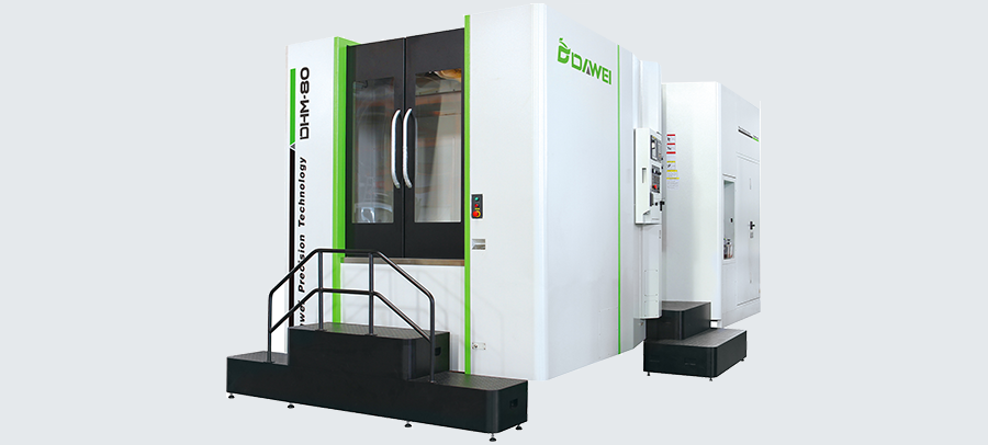
The perfect combination of the structure design technology of the thermal stability, whole machine’s thermogenic management technologies and thermal compensation technologies, has guaranteed the further improvement of the precision stability of the machine tool.

| Standard Configuration | Optional Configuration |
| Vertical Type | |
| FANUC CNC system | FANUC/Siemens/Heidenhain CNC Controller |
| BT40 8000rpm Spindle | BT/ISO/HSK-A63 10000~30000rpm Spindle |
| Spindle Belt Drive | Spindle Direct Drive |
| Spindle Oil Chiller | |
| Spindle coolant nozzle system | Coolant Through Spindle (CTS) |
| High Precision Screw rod | Coolant Through Screw rod |
| XYZ Axis Linear rails | |
| XYZ Axis Servo Motor | |
| Fully Enclosed Splash Guard | |
| Electrical Cabinet Heat Exchanger | Electrical Cabinet AC |
| Handheld air gun | |
| Water gun | |
| Automatic lubrication system | |
| LED working lamp | |
| Tool magazine | ATC/Tool Magazine system |
| CNC Manual & Operation | |
| Chip flush coolant system | |
| LCD | |
| Working lamp | |
| Three-color warning lamp | |
| Transformer(According to Local Voltage) | |
| Took kit | |
| The 4th axis rotary table | |
| spiral type Chip Conveyor system | |
| Chain type Chip Conveyor system | |
| Linear Scale | |
| Auto.Tool Measuring system | |
| Auto.Workpiece Measuring system | |
| CE Mark | |
| Others Options as requested |
High Rigidity
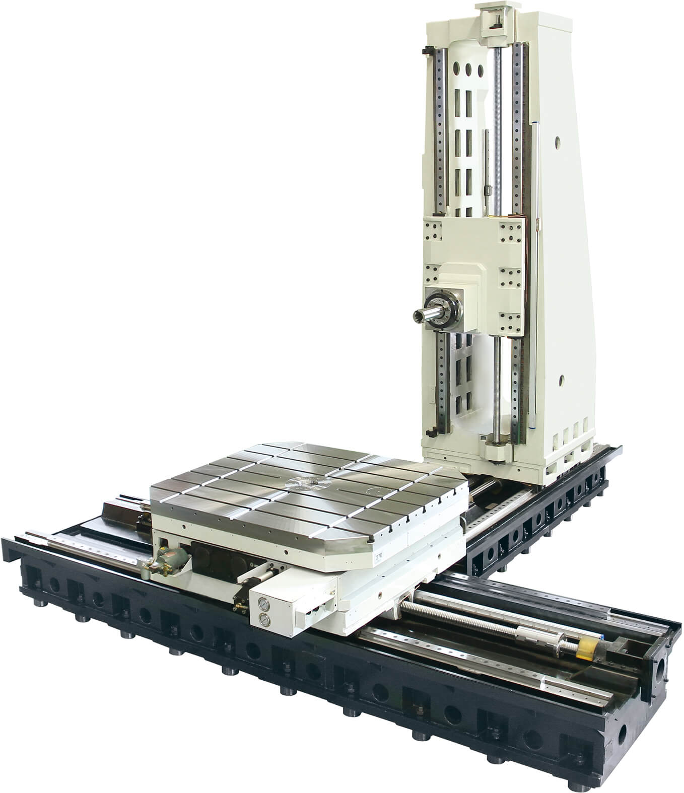
High Rigidity
“T” or “⊥” Structure
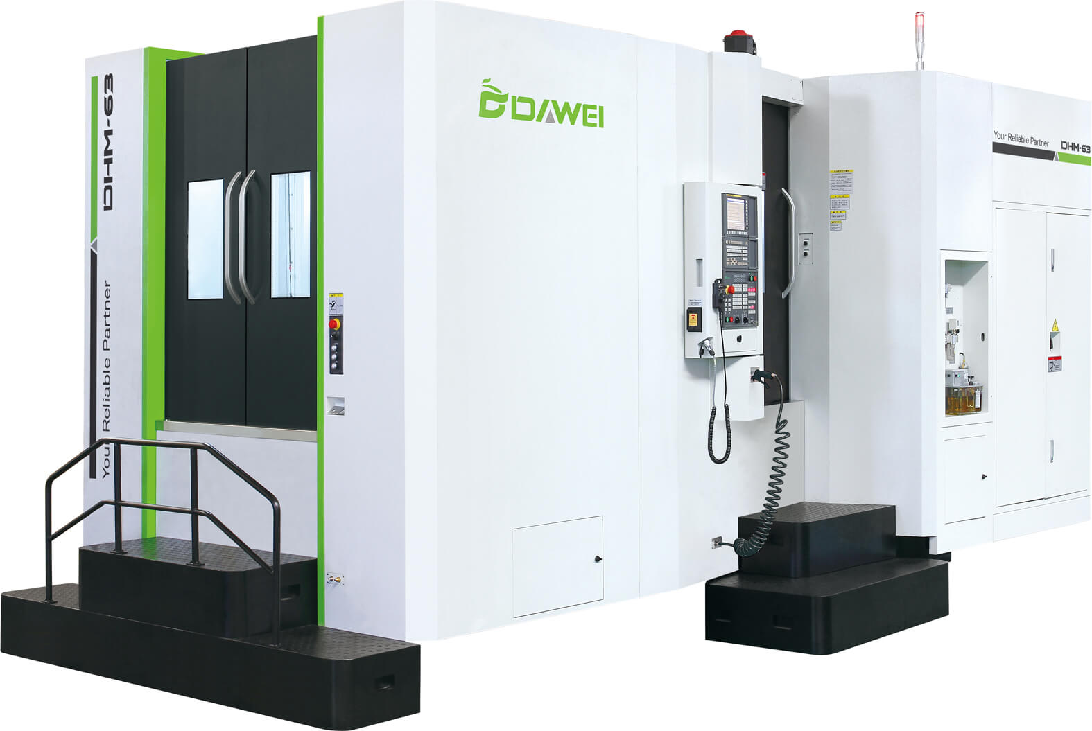
“T” or “⊥” Structure
The diverse frame of machining center meets the different demands from customers.
Cutting fluid coolant

Cutting fluid coolant
Multiple nozzles which directions can be adjusted are set on spindle ends to supply cutting fluid for machined parts as appropriate so as to improve machining precision.
Tool magazine
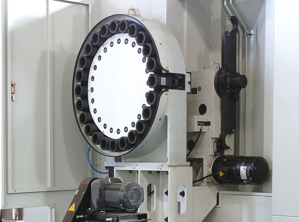
Tool Magazine
Automatic tool changer is composed of tool magazine and tool changing arms. Automatic tool changer is installed separately from machine tool with the purpose of preventing adverse influences of vibration during running of automatic tool changer and other reasons of precision. Tool selection adopts the method of fixed address in the shortest path. All tools return to original position, therefore, the problem of collision between large-size tools is only considered in initial installation. Two-way tool magazine adopts the shortest path.
Chip cleaning
Chip cleaning
Through the center slot from the spindle is directly below the discharge cutting, the shield makes the chip stacking, keep indoor clean processing.
-
Parameter table
DHM-40e(I) DHM-50(I) DHM-50(II) DHM-63(I) DHM-63(II) DHM-80(I) DHM-80(II) DHM-100(I) DHM-100(II) Travel X-axis travel mm 500 750 750 1050 1050 1300 1300 1600 1600 Y-axis travel mm 500 750 750 1000 1000 1200 1200 1300 1300 Z-axis travel mm 400 750 750 1000 1000 1200 1200 1300 1300 Spindle Spindle center to worktable surface mm 0-500 50-800 50-800 80-1080 80-1080 45-1245 45-1245 35-1335 35-1335 Spindle nose to work center mm 30-430 135-885 150-900 135-1135 135-1135 150-1350 150-1350 250-1550 250-1550 Spindle taper BT40 BT50 BT50 BT50 BT50 BT50 BT50 BT50 BT50 Rotating speed of spindle (standard) rpm/min 10000 6000 6000 6000 6000 6000 6000 6000 6000 Rotating speed of spindle (optional) rpm/min 12000 10000/12000 10000/12000 10000/12000 10000/12000 10000/12000 10000/12000 10000/12000 10000/12000 Transmission mode of spindle(standard) Direct-drive Direct-drive Direct-drive Belt + Gear box Belt + Gear box Belt + Gear box Belt + Gear box Belt + Gear box Belt + Gear box Transmission mode of spindle (optional) - Belt-drive / Belt + Gear box Belt-drive / Belt + Gear box Full gear wheel Full gear wheel Full gear wheel Full gear wheel Full gear wheel Full gear wheel Spindle & motor Spindle drive motor kW 7.5/11 11/18.5 11/18.5 18.5/22 18.5/22 22/26 22/26 22/26 22/26 Max. torque of spindle N・m 36/70 263/442 263/442 644/770 644/770 770/910 770/910 770/910 770/910 Rotary worktable (B axis) Pallet size (L×W) mm 400×400 500×500 500×500 630×630 630×630 800×800 800×800 1000×1000 1000×1000 Min. division angle deg 1°(Standard) / 0.001°(Optional) 0.001°(Standard) / 1°(Optional) 0.001°(Standard) / 1°(Optional) 0.001°(Standard) / 1°(Optional) 0.001°(Standard) / 1°(Optional) 0.001°(Standard) / 1°(Optional) 0.001°(Standard) / 1°(Optional) 0.001°(Standard) / 1°(Optional) 0.001°(Standard) / 1°(Optional) Reference aperture mm Φ55 H7 Φ55 H7 Φ55 H7 Φ55 H7 Φ55 H7 Φ55 H7 Φ55 H7 Φ55 H7 Φ55 H7 Max. load on worktable kg 350 600 600×2 1200 1200×2 2500 2000×2 2500 2000×2 Number of worktables pcs 1 1 2 1 2 1 2 1 2 Precision Worktable locating precision arc-sec 10″/10″(with optical ruler) 10″(with optical ruler)/ 10″ 10″(with optical ruler)/ 10″ 10″(with optical ruler)/ 10″ 10″(with optical ruler)/ 10″ 10″(with optical ruler)/ 10″ 10″(with optical ruler)/ 10″ 10″(with optical ruler)/ 10″ 10″(with optical ruler)/ 10″ Worktable repetitive precision arc-sec 2″/ 6″ 6″/ 2″ 6″/ 2″ 6″/ 2″ 6″/ 2″ 6″/ 2″ 6″/ 2″ 6″/ 2″ 6″/ 2″ Locating precision mm 0.012 0.012 0.012 0.012 0.012 0.012 0.012 0.012 0.012 Repetitive locating precision mm 0.008 0.008 0.008 0.008 0.008 0.008 0.008 0.008 0.008 Transmission mode Axial transmission mode Direct-drive Direct-drive Direct-drive Direct-drive Direct-drive Direct-drive Direct-drive Direct-drive Direct-drive Feed speed Cutting speed mm/min 1-10000 1-10000 1-10000 1-10000 1-10000 1-10000 1-10000 1-10000 1-10000 Rapid traverse speed X/Y/Z m/min 48/48/48 30/30/30 30/30/30 30/30/30 30/30/30 30/30/30 30/30/30 30/30/30 30/30/30 Tool magazine and automatic toolchanger Capacity of tool magazine 24 24(40/60) 24(40/60) 40(60) 40(60) 40(60) 40(60) 40(60) 40(60) Tool selecting mode Random Random Random Random Random Random Random Random Random Tool changing mode Arm type Arm type Arm type Arm type Arm type Arm type Arm type Arm type Arm type Max. tool weight kg 8 15 15 25 25 25 25 25 25 Max. tool length mm 300 350 350 500 500 600 600 600 600 Max. tool diameter (no adjacent tools) mm Φ85/125 Φ105/200 Φ105/200 Φ125/250 Φ125/250 Φ125/250 Φ125/250 Φ125/250 Φ125/250 Tool handle size BT40 BT50/CAT50/DIN50 BT50/CAT50/DIN50 BT50/CAT50/DIN50 BT50/CAT50/DIN50 BT50/CAT50/DIN50 BT50/CAT50/DIN50 BT50/CAT50/DIN50 BT50/CAT50/DIN50 Others Air pressure required kgf/cm2 6 6 6 6 6 6 6 6 6 Voltage requirements KVA 31 45 45 70 70 75 75 75 75 Tank capacity L 200 700 700 800 800 800 800 800 800 Machine weight kg 4500 14000 15000 19000 20000 20000 22000 23000 25000 Floor area (length*width) mm 2520×2075 5675×3625 6505×3625 6710×3940 7340×4100 6810×4025 8425×4190 6810×4815 8825×4815 Machine height mm 3025 3055 3055 3465 3465 3735 3735 3835 3835 -
High Rigidity
High Rigidity
The perfect combination of the structure design technology of the thermal stability, whole machine’s thermogenic management technologies and thermal compensation technologies, has guaranteed the further improvement of the precision stability of the machine tool.
-
“T” or “⊥” Structure
“T” or “⊥” Structure
The diverse frame of machining center meets the different demands from customers.
-
Cutting fluid coolant
Cutting fluid coolant
Multiple nozzles which directions can be adjusted are set on spindle ends to supply cutting fluid for machined parts as appropriate so as to improve machining precision.
-
Tool magazine
Tool Magazine
Automatic tool changer is composed of tool magazine and tool changing arms. Automatic tool changer is installed separately from machine tool with the purpose of preventing adverse influences of vibration during running of automatic tool changer and other reasons of precision. Tool selection adopts the method of fixed address in the shortest path. All tools return to original position, therefore, the problem of collision between large-size tools is only considered in initial installation. Two-way tool magazine adopts the shortest path.
-
Chip cleaning
Chip cleaning
Through the center slot from the spindle is directly below the discharge cutting, the shield makes the chip stacking, keep indoor clean processing.
- French
- German
- Portuguese
- Spanish
- Russian
- Japanese
- Korean
- Arabic
- Irish
- Greek
- Turkish
- Italian
- Danish
- Romanian
- Indonesian
- Czech
- Afrikaans
- Swedish
- Polish
- Basque
- Catalan
- Esperanto
- Hindi
- Lao
- Albanian
- Amharic
- Armenian
- Azerbaijani
- Belarusian
- Bengali
- Bosnian
- Bulgarian
- Cebuano
- Chichewa
- Corsican
- Croatian
- Dutch
- Estonian
- Filipino
- Finnish
- Frisian
- Galician
- Georgian
- Gujarati
- Haitian
- Hausa
- Hawaiian
- Hebrew
- Hmong
- Hungarian
- Icelandic
- Igbo
- Javanese
- Kannada
- Kazakh
- Khmer
- Kurdish
- Kyrgyz
- Latin
- Latvian
- Lithuanian
- Luxembou..
- Macedonian
- Malagasy
- Malay
- Malayalam
- Maltese
- Maori
- Marathi
- Mongolian
- Burmese
- Nepali
- Norwegian
- Pashto
- Persian
- Punjabi
- Serbian
- Sesotho
- Sinhala
- Slovak
- Slovenian
- Somali
- Samoan
- Scots Gaelic
- Shona
- Sindhi
- Sundanese
- Swahili
- Tajik
- Tamil
- Telugu
- Thai
- Ukrainian
- Urdu
- Uzbek
- Vietnamese
- Welsh
- Xhosa
- Yiddish
- Yoruba
- Zulu